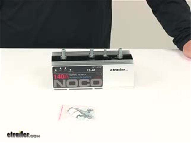
Noco Battery Isolator Instructions
A battery isolator is an important part of a multi-battery electrical system. When it is operating properly, it ensures that both vehicle batteries are charging when they should be, and that the vehicle's main battery will have enough juice to start the car in the event that the accessory battery has been drained. If the isolator is not operating properly, a number of problems can occur. Being able to troubleshoot an isolator may be the difference between your car starting or not starting at all.
May 07, 2015 This is a large item. It is about 11' long and the instructions say to mount it in a vertical way so it has air flow over the fins. (heat rises). The studs on the old 120A Sure Power isolator had 5/16' studs and the cables were sized to fit it. The new 200A isolator has 3/8' studs so the cable ends had to be enlarged to fit the larger studs. Noco Battery Isolator Installation Instructions NOCO IGK1440 Battery Isolator Installation Kit. Quick and easy installation (Comes with instructions), Box dimensions: 2” x 4” x 6”. View Cart ACCESSORIES. As well as if a few of itcome which has a manual, most consumers don't even care Online manuals usually provides. A battery isolator is an important part of a multi-battery electrical system. When it is operating properly, it ensures that both vehicle batteries are charging when they should be, and that the vehicle's main battery will have enough juice to start the car in the event that the accessory battery has been drained.
Step 1
Understand that a standard battery isolator has four contacts, two large contacts and two smaller ones. To start, disconnect the large gauge cables from the larger contacts. These cables lead to each battery's positive terminal, so care must be taken to keep the end of the cables from grounding out on the exposed metal of the engine compartment. Use the electrical tape to cover these ends.
Step 2
Place your meter leads on the large contacts that were previously attached to the batteries. Trigger the isolator to engage. Most triggers come from a switch or from the vehicle's ignition. Set your meter to ohms. A reading of 0 ohms indicates that the isolator is working. An open load reading indicates that it is not working.
Step 3
Visual basic 6.0 pdf download. If an open load is observed, test the triggers by disconnecting the wires going to them. Place an alligator clip on one trigger and connect the free end to ground. Connect the other alligator clip to the remaining trigger, and place its free end on a 12V source. You should feel and hear the isolator click and the meter should read 0 ohms. If there is no click, or if the meter still reads open load, replace the isolator.

If the isolator passes the test but you are still experiencing problems, you may have more serious electrical issues.
Tip
- Since you will be disconnecting the battery leads to test the isolator anyway, you may consider using this as an opportunity to clean your battery contacts and terminals. Your battery connections can never be too clean. Test your meter before you begin by measuring resistance across a clean piece of metal.
Warning
- Always observe proper safety procedures and equipment when working with or near a vehicle's battery.
Items you will need
Battery Isolator Diagram
- Digital multi-meter or a volt ohm meter
- Alligator clips
- Electrical tape
- Sockets